6. CYLINDER HEAD/VALVES GRAND DINK 125/150
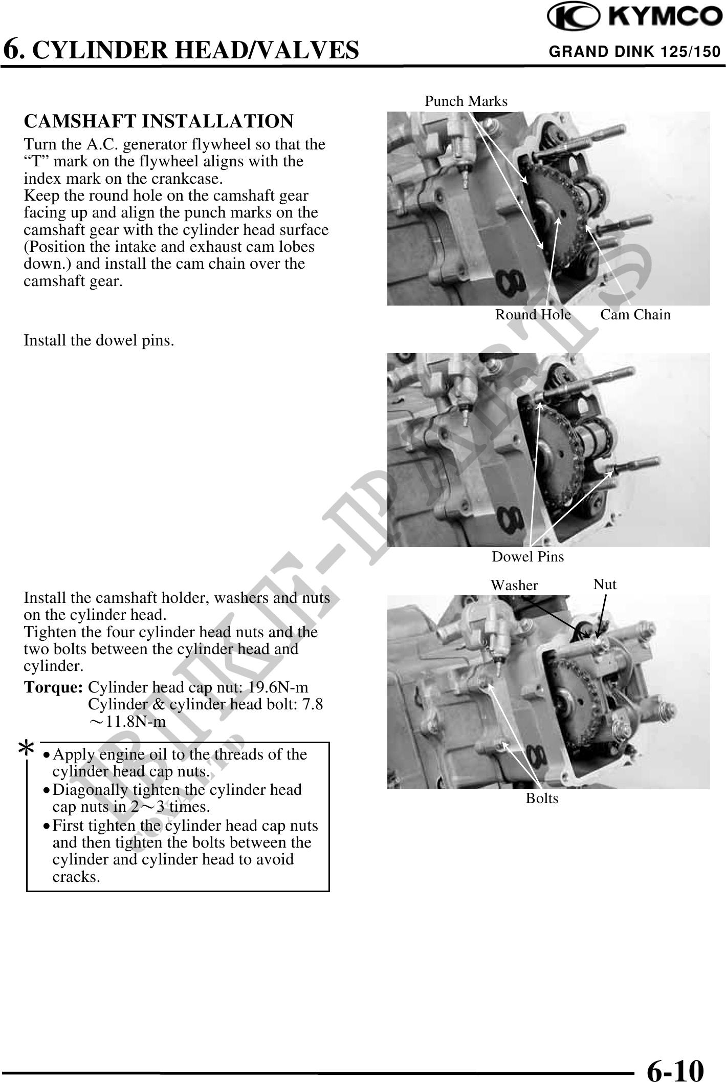
Punch Marks
CAMSHAFT INSTALLATION
Turn the A.C. generator flywheel so that the
"T" mark on the flywheel aligns with the
index mark on the crankcase.
Keep the round hole on the camshaft gear
facing up and align the punch marks on the
camshaft gear with the cylinder head surface
(Position the intake and exhaust cam lobes
down.) and install the cam chain over the
camshaft gear.
Round Hole Cam Chain
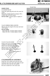
Install the dowel pins.
Dowel Pins
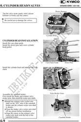
Washer Nut
Install the camshaft holder, washers and nuts
on the cylinder head.
Tighten the four cylinder head nuts and the
two bolts between the cylinder head and
cylinder.
Torque: Cylinder head cap nut: 19.6N-m
Cylinder & cylinder head bolt: 7.8
11.8N-m
· Apply engine oil to the threads of the
cylinder head cap nuts.
· Diagonally tighten the cylinder head Bolts
cap nuts in 23 times.
· First tighten the cylinder head cap nuts
and then tighten the bolts between the
cylinder and cylinder head to avoid
cracks.
6-10