7. CYLINDER HEAD/VALVES MXU 300/250
Cylinder Head Cover Bolts
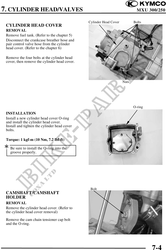
CYLINDER HEAD COVER
REMOVAL
Remove fuel tank. (Refer to the chapter 5)
Disconnect the crankcase breather hose and
pair control valve hose from the cylinder
head cover. (Refer to the chapter 6)
Remove the four bolts at the cylinder head
cover, then remove the cylinder head cover.
Nuts
O-ring
INSTALLATION
Install a new cylinder head cover O-ring
and install the cylinder head cover.
Install and tighten the cylinder head cover
bolts.
Torque: 1 kgf-m (10 Nm, 7.2 lbf-ft)
Be sure to install the O-ring into the
groove properly.
Bolt
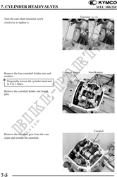
CAMSHAFT/CAMSHAFT
HOLDER
REMOVAL
Remove the cylinder head cover. (Refer to
the cylinder head cover removal)
Remove the cam chain tensioner cap bolt
and the O-ring.
7-4