13. BRAKE SYSTEM MXU 300/250
ASSEMBLY
Before assembly, apply brake fluid to all
removed parts.
· During assembly, the main piston and
spring must be installed as a unit
without exchange.
· When assembling the piston, soak the
cups in brake fluid for a while.
· Install the cups with the cup lips facing
the correct direction.
Install the main piston, spring and snap ring.
Install the rubber cover.
Install the brake lever.
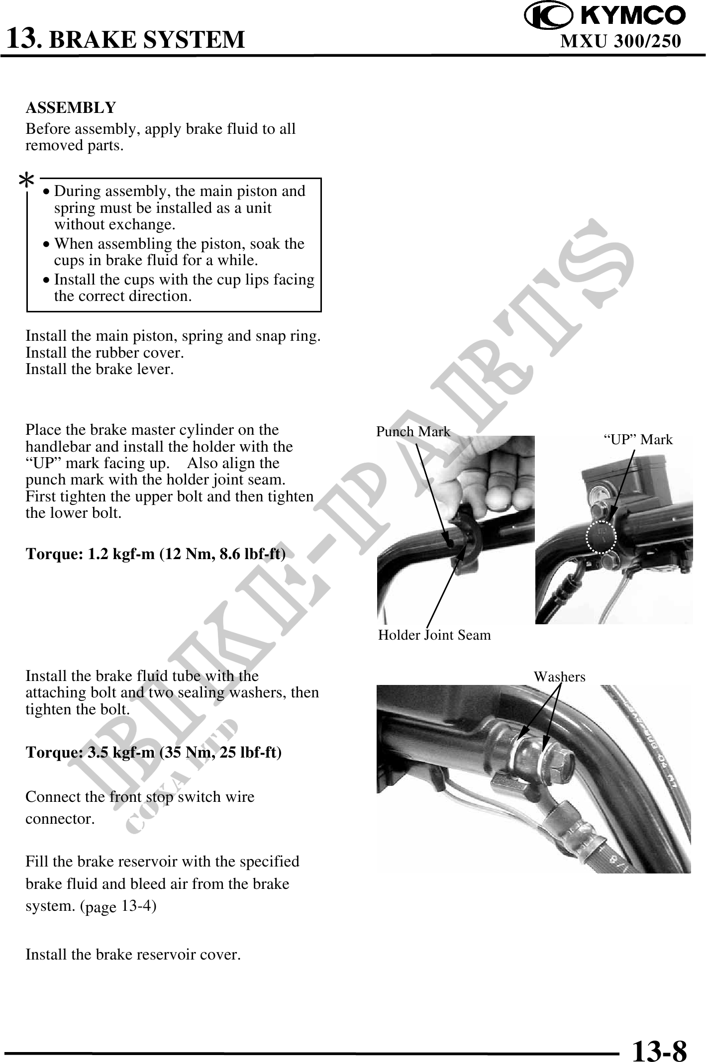
Place the brake master cylinder on the Punch Mark
handlebar and install the holder with the "UP" Mark
"UP" mark facing up. Also align the
punch mark with the holder joint seam.
First tighten the upper bolt and then tighten
the lower bolt.
Torque: 1.2 kgf-m (12 Nm, 8.6 lbf-ft)
Holder Joint Seam
Install the brake fluid tube with the Washers
attaching bolt and two sealing washers, then
tighten the bolt.
Torque: 3.5 kgf-m (35 Nm, 25 lbf-ft)
Connect the front stop switch wire
connector.
Fill the brake reservoir with the specified
brake fluid and bleed air from the brake
system. (page 13-4)
Install the brake reservoir cover.
13-8