14. FRONT WHEEL/FRONT SUSPENSION/
STEERING SYSTEM MXU 300/250
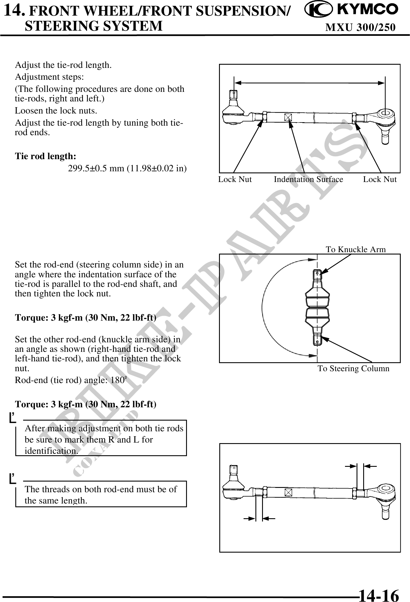
Adjust the tie-rod length.
Adjustment steps:
(The following procedures are done on both
tie-rods, right and left.)
Loosen the lock nuts.
Adjust the tie-rod length by tuning both tie-
rod ends.
Tie rod length:
299.50.5 mm (11.980.02 in)
Lock Nut Indentation Surface Lock Nut
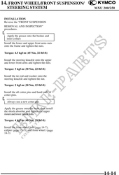
To Knuckle Arm
Set the rod-end (steering column side) in an
angle where the indentation surface of the
tie-rod is parallel to the rod-end shaft, and
then tighten the lock nut.
Torque: 3 kgf-m (30 Nm, 22 lbf-ft)
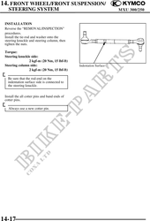
Set the other rod-end (knuckle arm side) in
an angle as shown (right-hand tie-rod and
left-hand tie-rod), and then tighten the lock
nut. To Steering Column
Rod-end (tie rod) angle: 180
Torque: 3 kgf-m (30 Nm, 22 lbf-ft)
After making adjustment on both tie rods
be sure to mark them R and L for
identification.
The threads on both rod-end must be of
the same length.
14-16