mxu 250 300 2 Werkstatthandbuch : Seite 322

Microfiches
Image preview

Seite 320

Image preview

Seite 321

Image preview

Seite 323

Image preview

Seite 324

1 5 10 15 20 25 30 35 40 45 50 55 60 65 70 75 80 85 90 95 100 105 110 115 120 125 130 135 140 145 150 155 160 165 170 175 180 185 190 195 200 205 210 215 220 225 230 235 240 245 250 255 260 265 270 275 280 285 290 295 300 305 310 315 320 325 330 335 340 345 350 352
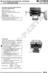
          16. BATTERY/CHARGING SYSTEM/
    A.C. GENERATOR                                                              MXU 300/250

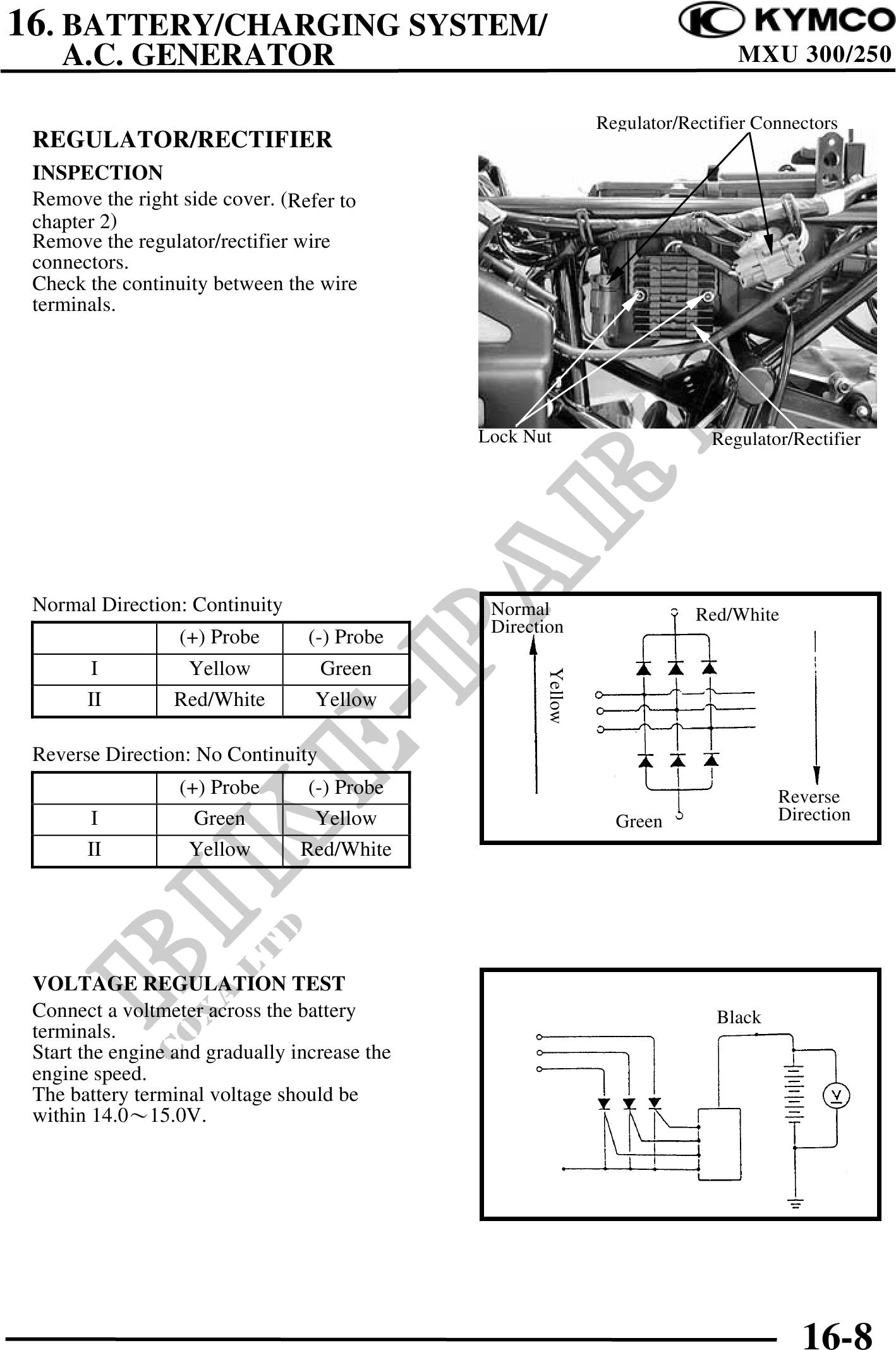
                                                               Regulator/Rectifier Connectors
 REGULATOR/RECTIFIER
 INSPECTION
 Remove the right side cover. (Refer to
 chapter 2)
 Remove the regulator/rectifier wire
 connectors.
 Check the continuity between the wire
 terminals.


                                               Lock Nut                      Regulator/Rectifier


 Normal Direction: Continuity                   Normal                     Red/White
                                                Direction
                 (+) Probe        (-) Probe
        I         Yellow            Green
                                                      Yellow


       II        Red/White         Yellow

 Reverse Direction: No Continuity
                  (+) Probe       (-) Probe                                          Reverse
        I           Green          Yellow                        Green               Direction
       II          Yellow        Red/White


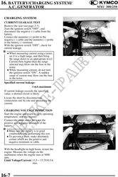
 VOLTAGE REGULATION TEST
 Connect a voltmeter across the battery                                      Black
 terminals.
 Start the engine and gradually increase the
 engine speed.
 The battery terminal voltage should be
 within 14.015.0V.


                                                                                        16-8