5. FUEL SYSTEM MXU 300/250
ASSEMBLY
Install the slow jet.
Install the needle jet, needle jet holder and
main jet.
Install the throttle stop screw and air screw
Install the spring, diaphragm and O-rings.
· When installing the air screw, return it
to the original position as noted during
removal
· After the carburetor is installed, be
sure to perform the Exhaust Emission
Install the float valve, float and float pin.
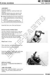
FLOAT LEVEL INSPECTION
Turn the carburetor upside down so that the
float will go down to make the float valve
contact the float valve seat.
Then slowly tilt the carburetor and measure
the float level with the float level gauge
while the float pin just contacts with float
valve.
Float Level: 14.8mm
When adjusting, carefully bend the float pin.
Check the float for proper operation.
Install the jet holder, aligning the baffle plate
groove with the carburetor tab and then
install the float chamber.
INSTALLATION
Reverse the " CARBURETOR REMOVAL"
procedures.
Baffle Plate
AIR CLEANER
Refer to the "AIR CLEANER" section in the
chapter 3 for air cleaner replacement and
cleaning.
5-14