15. IGNITION SYSTEM GP 125i
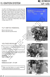
Use DC 8-16V Battery power, it is with 3 pins: one
power pin, one signal output pin and one earthing
pin. When vehicle tilted to more than 65 deg. The
signal line will be earthed so that ECU can tell that
the vehicle is tilting and further cut fuel supply and
ignition. When the vehicle is reset up, it shall go
through Key Off and Key On to return to normal
status. It is comprised of Hall Effect with output
voltage range of 0-14V.
Bolts
TILT SWITCH REMOVAL
Remove the front cover.
Remove the bolts and Tilt switch.
Tilt Switch
VOLTAGE MEASURE
This purpose is that inspect the input/output
voltage if normal.
Connect the multimeter (+) probe to the pink/red
wire and the multimeter (-) probe to the green wire
to measure the input voltage.
Standard:
Input voltage : 5 ~ 6 V
Tilt switch connector
Standard:
Fall down is over 65° : 3.7~4.4V
Make sure that battery is in good condition
before performing this measurement.
Tilt switch
15-5