mxu 400 Werkstatthandbuch : Seite 51

Microfiches
Image preview

Seite 49

Image preview

Seite 50

Image preview

Seite 52

Image preview

Seite 53

1 5 10 15 20 25 30 35 40 45 50 55 60 65 70 75 80 85 90 95 100 105 110 115 120 125 130 135 137
                                                            CF060A                                                     MD1343A
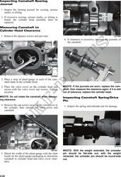
 2. If damaged, the camshaft must be replaced.                               ! CAUTION
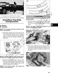
                                                            Incorrect installation of the piston rings will result in
                                                            engine damage.
     Installing Top-Side
                                                            1. Install the piston on the connecting rod making
        Components                                             sure there is a circlip on each side and the open
                                                               end of the circlip is directed upwards or down-

A. Piston
                                                               wards.
                                                             NOTE: The piston should be installed so the
                                                                                                                        3
B. Cylinder
                                                            arrow points towards the exhaust.
  NOTE: If the piston rings were removed, install
them in this sequence.

   A. Install ring expander (4) in the bottom groove
      of the piston; then install the thin oil rings (3)
      over the expander making sure the expander
      ends do not overlap. Stagger the end gaps of the
      upper and lower thin oil rings according to the
      illustration.


                                                                                                               MD1213
                                                            2. Place the two alignment pins into position. Place a
                                                               new cylinder gasket into position; then place a pis-
                                                               ton holder (or suitable substitute) beneath the pis-
                                                               ton skirt and square the piston in respect to the
                                                               crankcase.


                                                ATV-1085B

  NOTE: Note the direction of the exhaust side of
the piston (5) for correct ring end gap orientation.

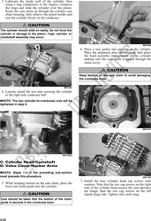
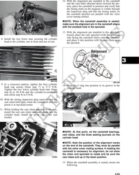
   B. Install the compression rings (1 and 2) so the
      letter(s) on the top surface of each ring faces the
      top of the piston. Rotate the rings until the ring
      end gaps are on directly opposite sides of the
      piston according to the illustration.
  NOTE: The chrome (silver) ring should be
                                                                                                               MD1344
installed in the top position.


                                                                                                                3-21