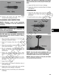
NOTE: If the slow jet is obstructed, the mixture
will be extremely lean at idle and part-throttle oper-
ation.
11. Inspect the float valve for wear or damage.
12. Inspect the carburetor mounting flange for damage
and tightness.
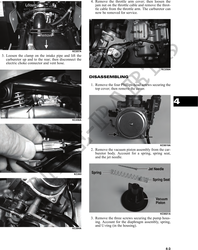
ASSEMBLING
1. Thread the idle adjust screw into the carburetor
making sure the washer and spring are properly
KC0029A positioned.
10. Unscrew and remove the idle adjust screw. 2. Install the pilot screw, spring, washer, and O-ring.
Account for the spring and washer.
CLEANING AND INSPECTING
NOTE: Whenever a part is worn excessively,
cracked, or damaged in any way, replacement is
necessary.
! WARNING
When drying components with compressed air,
always wear safety glasses.
4
! CAUTION
DO NOT place any non-metallic components in KC0029A
parts-cleaning solvent because damage or deterio-
ration will result.
1. Place all metallic components in a wire basket and
submerge in carburetor cleaner.
2. Soak for 30 minutes; then rinse with clean, hot
water.
3. Wash all non-metallic components with soap and
water. Rinse thoroughly.
4. Dry all components with compressed air only
making sure all holes, orifices, and channels are
unobstructed. KC0028A
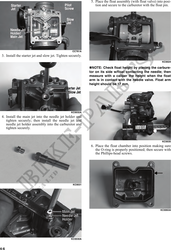
NOTE: Turn the pilot screw clockwise until it is
5. Inspect the carburetor body for cracks, nicks,
stripped threads, and any imperfections in the cast- lightly seated; then turn it counterclockwise the rec-
ing. ommended number of turns as an initial setting.
6. Inspect the vacuum piston/diaphragm for cracks, NOTE: Note the locations of the jets and holder
imperfections in the casting, or cracks and tears in during assembling procedures.
the rubber.
7. Inspect float for damage.
8. Inspect gasket and O-rings for distortion, tears, or
noticeable damage.
9. Inspect tips of the jet needle, pilot screw, and the
needle jet for wear, damage, or distortion.
10. Inspect the slow jet and main jet for obstructions
or damage.
4-5