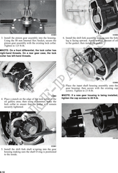
NOTE: If gears are being replaced, use the exist- B. Gear Case Side - install a 1.3-1.4 mm shim and
ing shims. The numbers are scribed onto the tighten the bolts to 25-31 ft-lb. Verify backlash
gears: the ring gear has the number on the oppo- to be within a range of 0.28-0.38 mm
site side of the gears, and the pinion gear has the (0.011-0.015 in.) and end-play to be within a
number on the end of the pinion gear shaft by the range of 0.10-0.20 mm (0.004-0.008 in.). If not
splines. If no number is present, it should be con- within specification range, reselect shim until
sidered as being in the 0 category.
backlash specification range can be verified.
4. Prior to final assembling, apply molybdenum dis-
NOTE: If the gear case housing is being replaced, ulfide grease to all oil seal lips.
proceed to the following Shimming Proce-
dure/Shim Selection sub-section. 5. Prior to final assembling, prelubricate journal on
pinion assembly with SAE 80W-90 hypoid gear
Shimming Procedure/Shim lubricant prior to pressing assembly into gear case
Selection housing.
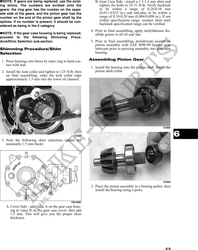
1. Press bearings into bores by outer ring to hard con- Assembling Pinion Gear
tact with seat.
1. Install the bearing onto the pinion shaft. Install the
2. Install the lock collar and tighten to 125 ft-lb; then pinion shaft collar.
on final assembling, stake the lock collar edge
approximately 1.5 mm into the lower oil channel.
CC882
CC891 6
3. Note the following shim selections (shims are
nominally 1.5 mm thick):
CC883
2. Place the pinion assembly in a bearing puller; then
install the bearing using a press.
738-268C
A. Cover Side - add value A on the gear case hous-
ing to value B on the gear case cover; then add
1.5 mm. This will give you the proper shim
thickness.
6-9