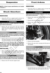
6. Secure the brake caliper to the knuckle with the
two cap screws (right side only). Tighten the cali-
per to 20 ft-lb.
7. Compress the hand brake lever and engage the
brake lever lock; then secure the hub nut (from
step 5) to the drive axle. Tighten to 200 ft-lb.
8. Install a new cotter pin and spread the pin to
secure the nut.
9. Secure the shock absorber to the frame with a cap
screw and new lock nut. Tighten to 35 ft-lb.
KC0100 10. Secure the shock absorber to the lower A-arm with
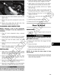
7. Slide the hub out of the knuckle and set aside. a cap screw and new lock nut. Tighten to 20 ft-lb.
8. Remove the cap screws and lock nuts securing the 11. Secure the boot guard to the lower A-arm with the
knuckle to the A-arms. Discard the lock nuts. two cap screws. Tighten securely.
NOTE: Never reuse a lock nut. Once a lock nut 12. Install the wheel and tighten to 40 ft-lb.
has been removed, it must be replaced with a new
13. Remove the ATV from the support stand.
lock nut.
9. Remove the cap screws and lock nuts securing the
A-arms to the frame; then remove the A-arms. Wheels and Tires
NOTE: If removing the upper right A-arm, it will
be necessary to disconnect the brake hose from
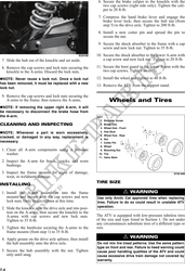
the A-arm. KEY
1. Shoulder Screw
CLEANING AND INSPECTING 2. Brake Disc
3. Wheel Hub - Front
NOTE: Whenever a part is worn excessively, 4. Hub Stud
5. Wheel Hub - Rear
cracked, or damaged in any way, replacement is 6. Nut
necessary. 7. Cotter Pin
8. Wheel
1. Clean all A-arm components using a pressure 9. Mounting Nut
washer. 10. Tire
11. Valve Stem
2. Inspect the A-arm for bends, cracks, and worn
bushings.
3. Inspect the frame mounts for signs of damage, 0742-948
wear, or weldment damage.
TIRE SIZE
INSTALLING
1. Install the A-arm assemblies into the frame ! WARNING
mounts and secure with the cap screws and new Use only Arctic Cat approved tires when replacing
lock nuts. Only finger-tighten at this time. tires. Failure to do so could result in unstable ATV
operation.
2. Slide the knuckle onto the drive axle and into posi-
tion on the A-arms; then secure the knuckle to the
A-arms with cap screws and new lock nuts. The ATV is equipped with low-pressure tubeless tires
Tighten to 35 ft-lb. of the size and type listed in Section 1. Do not under
any circumstances substitute tires of a different type or
3. Tighten the hardware securing the A-arms to the size.
frame mounts (from step 1) to 35 ft-lb.
4. Apply grease on the drive axle splines; then install
! WARNING
the hub assembly onto the drive axle. Do not mix tire tread patterns. Use the same pattern
type on front and rear. Failure to heed warning could
5. Secure the hub assembly with the nut. Tighten cause poor handling qualities of the ATV and could
only until snug. cause excessive drive train damage not covered by
warranty.
7-4