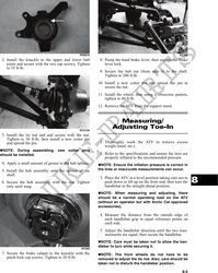
6. Using a permanent marker of some type, mark the CLEANING AND INSPECTING
center of each front tire (at a height parallel to the
belly panel). NOTE: Whenever a part is worn excessively,
cracked, or damaged in any way, replacement is
necessary.
1. Clean all rack components using a pressure
washer.
2. Inspect all welds for cracking or bending.
3. Inspect threaded areas of all mounting bosses for
stripping.
4. Inspect for missing decals and/or reflectors.
INSTALLING
AF789D
1. Place the rack into position on the frame and front
7. Measure the distance between the marks (at a fender panel. Install the cap screws and lock nuts
height parallel to the belly panel) at the front side; and finger-tighten only.
then record the measurement.
2. Install the two cap screws and lock nuts securing
8. Push the ATV forward until the marks are parallel the rack to the fenders. Tighten all hardware
to the belly panel on the back side; then measure securely.
the distance between the marks.
9. The difference in the measurements must show
1/8-1/4 in. toe-in (the front measurement 1/8-1/4
in. less than the rear measurement).
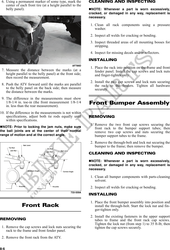
Front Bumper Assembly
10. If the difference in the measurements is not within
specifications, adjust both tie rods equally until REMOVING
within specifications.
1. Remove the two front cap screws securing the
NOTE: Prior to locking the jam nuts, make sure front rack to the bumper support tubes; then
the ball joints are at the center of their normal remove two cap screws and nuts securing the
range of motion and at the correct angle. bumper support tubes to the frame.
2. Remove the through-bolt and lock nut securing the
bumper to the frame; then remove the bumper.
CLEANING AND INSPECTING
NOTE: Whenever a part is worn excessively,
cracked, or damaged in any way, replacement is
necessary.
1. Clean all bumper components with parts-cleaning
solvent.
2. Inspect all welds for cracking or bending.
733-559A
INSTALLING
1. Place the front bumper assembly into position and
Front Rack install the through-bolt. Start the lock nut and fin-
ger-tighten only.
2. Install the existing fasteners in the upper support
REMOVING tubes to frame and the front rack cap screws.
Tighten the lock nut (from step 1) to 35 ft-lb; then
1. Remove the cap screws and lock nuts securing the tighten the cap screws securely.
rack to the frame and front fender panel.
2. Remove the front rack from the ATV.
8-6