KC210G KC224
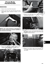
7. Remove the front body panel/fender panel. 3. Install the screws securing the front body to the
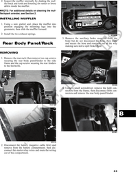
front body supports; then install the left-side and
CLEANING AND INSPECTING right-side footwell fasteners. Do not tighten at this
time.
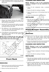
NOTE: Whenever a part is worn excessively,
cracked, or damaged in any way, replacement is 4. Place the gas tank cover into position and secure
necessary. with the existing hardware; then install the two cap
screws securing the rear of the panel to the frame.
1. Clean all fender components with warm soap and Tighten all cap screws and fasteners securely at
water. this time.
2. Inspect fenders for cracks and/or loose rivets. 5. Install the electric panel, side panels, and seat.
3. Inspect for any missing decals.
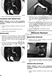
INSTALLING Exhaust System
1. Making sure the shift spring is in place and the
shift lever is properly positioned, place the front REMOVING MUFFLER
body panel/fender panel onto the ATV. With the
front rack in place, loosely install the front rack 1. Remove the two exhaust springs at the muf-
hardware. fler/exhaust pipe juncture.
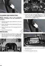
2. Connect the electrical connectors under the elec-
tric panel; then connect the light connectors and
attach onto the frame.
KC170
2. Slide the muffler rearward to clear the mounting
lugs and remove the muffler. Account for a grafoil
KC210G seal.
INSPECTING MUFFLER
NOTE: Whenever a part is worn excessively,
cracked, or damaged in any way, replacement is
necessary.
1. Inspect muffler externally for cracks, holes, and
dents.
8-8