5. FUEL INJECTION SYSTEM MXU 500EXi/MXU500i
TPS INSPECTION
Support the ATV on a level surface.
Turn the ignition switch to "ON".
Measure if the ECU voltage outputs to TPS
between the following terminals of the TPS
connector.
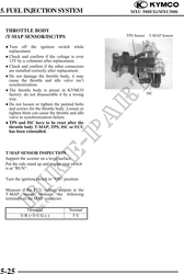
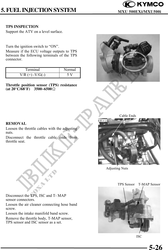
Terminal Normal
V/R (+) -V/G(-) 5V
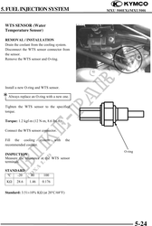
Throttle position sensor (TPS) resistance
(at 20°C/68°F) 3500~6500
Cable Ends
REMOVAL
Loosen the throttle cables with the adjusting
nuts.
Disconnect the throttle cable ends from
throttle seat.
Adjusting Nuts
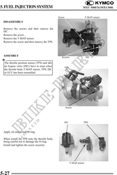
TPS Sensor T-MAP Sensor
Disconnect the TPS, ISC and T- MAP
sensor connectors.
Loosen the air cleaner connecting hose band
screw.
Loosen the intake manifold band screw.
Remove the throttle body, T-MAP sensor,
TPS sensor and ISC sensor as a set.
ISC
5-26