17. LIGHTS/INSTRUMENTS/SWITCHES PEOPLE 125/150
If the needle remains at "", it indicates that
the resistor is faulty and must be replaced.
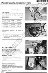
Fuel Unit Connector
INSPECTION
Measure the resistance between the fuel unit
wire terminals with the float at upper and
lower positions.
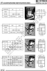
RESISTANCES Unit:
Float Upper Lower
Color
G Y/W 26 38 450 550
G L/W 450 550 26 38
Y/W L/W 450 550 450 550
The installation sequence is the reverse of
removal.
· Install the fuel unit by aligning the
groove on the fuel unit with the tab on
the fuel tank.
AUTO BYSTARTER
AUTO BYSTARTER INSPECTION
Remove the rear right side cover. ( 2)
Disconnect the auto bystarter wire connector.
Measure the resistance between the yellow
and green/black wire terminals.
Resistance: 10 max.
Perform this operation when the engine
is cold.
Auto Bystarter Connector
RESISTOR INSPECTION
Remove the front cover. ( 2)
Disconnect the green/black and green wires
and measuring the resistance between the
wire terminals.
Resistance: 5 max.
17-7