16. BATTERY/CHARGING SYSTEM
CHARGING SYSTEM
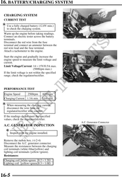
CURRENT TEST
Use a fully charged battery (12.8V min.)
to check the charging system.
Warm up the engine before taking readings.
Connect an electric tester across the battery Red Wire
terminals.
Disconnect the red wire from the fuse
terminal and connect an ammeter between the
red wire lead and the fuse terminal.
Attach a tachometer to the engine.
Start the engine and gradually increase the
engine speed to measure the limit voltage and
current.
Limit Voltage/Current: 1415V/0.5A max.
(5000rpm max.)
If the limit voltage is not within the specified
range, check the regulator/rectifier.
PERFORMANCE TEST
Engine Speed 2500rpm 6000rpm
Charging Current 1.3A min. 2.0A min.
When measuring the charging current,
disconnect the wire from the
regulator/rectifier wire coupler.
If the readings do not meet the specified
values, check the regulator/rectifier.
A.C. Generator Connector
A.C. GENERATOR INSPECTION
Inspect with the engine installed.
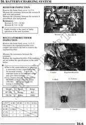
Remove the met-in box. ( 2-4)
Disconnect the A.C. generator connector.
Measure the resistances between the charging
coil terminals (whiteblue/yellow) and
lighting coil terminals (yellowgreen).
Resistances:
Charging coil whitegreen 0.21.2
Lighting coil yellowgreen 0.31.0
16-5