2. EXHAUST MUFFLER/FRAME COVERS
Screws
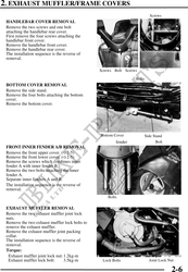
HANDLEBAR COVER REMOVAL
Remove the two screws and one bolt
attaching the handlebar rear cover.
First remove the four screws attaching the
handlebar front cover.
Remove the handlebar front cover.
Remove the handlebar rear cover.
The installation sequence is the reverse of
removal.
Screws Bolt Screws
Bolts
BOTTOM COVER REMOVAL
Remove the side stand.
Remove the four bolts attaching the bottom
cover.
Remove the bottom cover.
Bottom Cover Side Stand
fender Bolt
FRONT INNER FENDER A/B REMOVAL
Remove the front upper cover. ( 2-5)
Remove the front lower cover. ( 2-5)
Remove the screws which combines inner
fender A with inner fender B.
Remove the two bolts attaching the inner
fender A.
Separate inner fenders A and B.
The installation sequence is the reverse of
removal.
Bolts
EXHAUST MUFFLER REMOVAL
Remove the two exhaust muffler joint lock
nuts.
Remove the two exhaust muffler lock bolts to
remove the exhaust muffler.
Remove the exhaust muffler joint packing
collar.
The installation sequence is the reverse of
removal.
Torque:
Exhaust muffler joint lock nut: 1.2kg-m
Exhaust muffler lock bolt: 3.5kg-m Lock Bolts Joint Lock Nut
2-6