5. FUEL INJECTION SYSTEM MXU 500EXi/MXU500i
TILT SWITCH(ROLL SENSOR)
INSPECTION
Support the ATV level surface.
Turn the ignition switch to "OFF"
Remove the screws, washers and tilt switch.
Do not disconnect the tilt switch
connector during inspection.
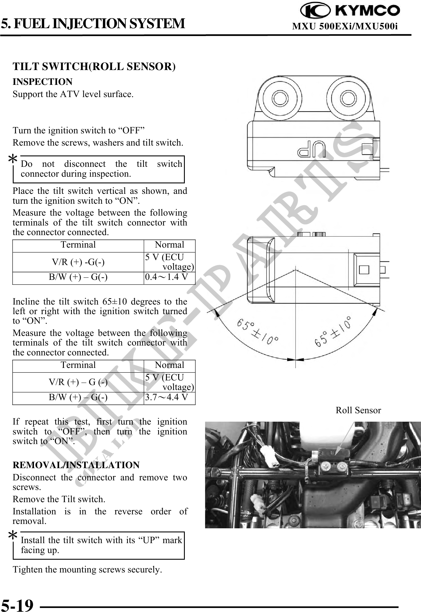
Place the tilt switch vertical as shown, and
turn the ignition switch to "ON".
Measure the voltage between the following
terminals of the tilt switch connector with
the connector connected.
Terminal Normal
5 V (ECU
V/R (+) -G(-) voltage)
B/W (+) G(-) 0.41.4 V
Incline the tilt switch 6510 degrees to the
left or right with the ignition switch turned
to "ON".
Measure the voltage between the following
terminals of the tilt switch connector with
the connector connected.
Terminal Normal
5 V (ECU
V/R (+) G (-) voltage)
B/W (+) G(-) 3.74.4 V
Roll Sensor
If repeat this test, first turn the ignition
switch to "OFF", then turn the ignition
switch to "ON".
REMOVAL/INSTALLATION
Disconnect the connector and remove two
screws.
Remove the Tilt switch.
Installation is in the reverse order of
removal.
Install the tilt switch with its "UP" mark
facing up.
Tighten the mounting screws securely.
5-19