mxu 550 exi Werkstatthandbuch : Seite 186

Microfiches
Image preview

Seite 184

Image preview

Seite 185

Image preview

Seite 187

Image preview

Seite 188

1 5 10 15 20 25 30 35 40 45 50 55 60 65 70 75 80 85 90 95 100 105 110 115 120 125 130 135 140 145 150 155 160 165 170 175 180 185 190 195 200 205 210 215 220 225 230 235 240 245 250 255 260 265 270 275 280 285 290 295 300 305 310 315 320 325 330 335 340 345 350 355 360 365 370 375 380 385 390 395 400 405 410 415 420 422
          8. CYLINDER HEAD/VALVES                                        MXU 550EXi /MXU500i


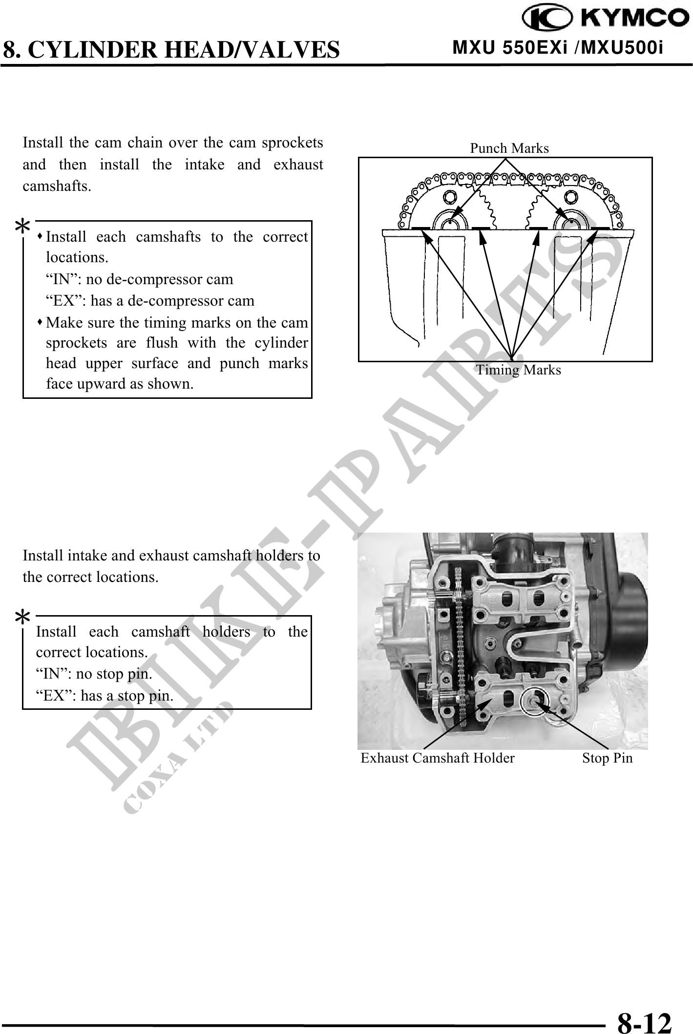
 Install the cam chain over the cam sprockets                     Punch Marks
 and then install the intake and exhaust
 camshafts.

    Install each camshafts to the correct
    locations.
    "IN": no de-compressor cam
    "EX": has a de-compressor cam
    Make sure the timing marks on the cam
    sprockets are flush with the cylinder
    head upper surface and punch marks                             Timing Marks
    face upward as shown.


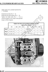
 Install intake and exhaust camshaft holders to
 the correct locations.


   Install each camshaft holders to the
   correct locations.
   "IN": no stop pin.
   "EX": has a stop pin.


                                                  Exhaust Camshaft Holder         Stop Pin


                                                                                       8-12