mxu 550 exi Werkstatthandbuch : Seite 244

Microfiches
Image preview

Seite 242

Image preview

Seite 243

Image preview

Seite 245

Image preview

Seite 246

1 5 10 15 20 25 30 35 40 45 50 55 60 65 70 75 80 85 90 95 100 105 110 115 120 125 130 135 140 145 150 155 160 165 170 175 180 185 190 195 200 205 210 215 220 225 230 235 240 245 250 255 260 265 270 275 280 285 290 295 300 305 310 315 320 325 330 335 340 345 350 355 360 365 370 375 380 385 390 395 400 405 410 415 420 422
          11.FINAL REDUCTION/
   TRANSMISSION SYSTEM                                    MXU 550EXi/MXU500i


 SECONDARY DRIVE/DRIVEN
 BEVEL GEAR
 REMOVAL/INSPECTION/INSTAL
 LATION

 REMOVAL

 Drain engine oil into a clean container. (Refer
 to the "ENGINE OIL" section in the chapter
 3).
 Move the engine assembly forward (refer to
 the "ENGINE REMOVAL" section in the
 chapter 6) or remove the rear propeller (refer
 to the "REAR PROPELLER SHAFT
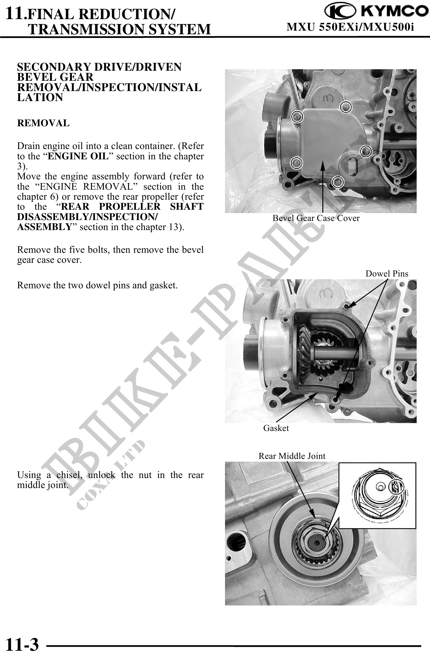
 DISASSEMBLY/INSPECTION/                              Bevel Gear Case Cover
 ASSEMBLY" section in the chapter 13).

 Remove the five bolts, then remove the bevel
 gear case cover.
                                                                              Dowel Pins
 Remove the two dowel pins and gasket.


                                                    Gasket


                                                   Rear Middle Joint

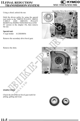
 Using a chisel, unlock the nut in the rear
 middle joint.


11-3