spacer 50 125 1 Werkstatthandbuch : Seite 211

Microfiches
Image preview

Seite 209

Image preview

Seite 210

Image preview

Seite 212

Image preview

Seite 213

1 5 10 15 20 25 30 35 40 45 50 55 60 65 70 75 80 85 90 95 100 105 110 115 120 125 130 135 140 145 150 155 160 165 170 175 180 185 190 195 200 205 210 215 220 225 230 232
          19. SWITCHES/HORN/FUEL UNIT/THERMOSTATIC SWITCH
    /TEMPERATURE GAUGE/INSTRUMENTS/LIGHTS
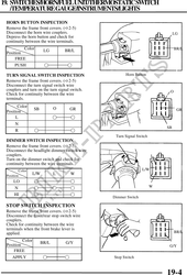
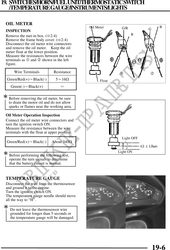
 HORN BUTTON INSPECTION
 Remove the frame front covers. ( 2-5)
 Disconnect the horn wire couplers.                                            LG
 Depress the horn button and check for
 continuity between the wire terminals.
          Color                                                                BR/L
                        LG        BR/L
 Position
      FREE
      PUSH                         

 TURN SIGNAL SWITCH INSPECTION                        Horn Button
 Remove the frame front covers. ( 2-5)
 Disconnect the turn signal switch wire
 couplers and turn on the turn signal switch.                              O
 Check for continuity between the wire
 terminals.
       Color                  O
                  SB                 GR                                         GR
 Position
      L                              
      N
                                                                          SB
      R                              
                                                 Turn Signal Switch
 DIMMER SWITCH INSPECTION
 Remove the frame front covers. ( 2-5)
 Disconnect the headlight dimmer switch wire
 couplers.                                                            L
 Turn on the dimmer switch and check for
 continuity between the wire terminals.
         Color                                                  L/W
 Position
                  L/W         L      W
     LO                              
     N                                                                W

     HI                              
                                                Dimmer Switch

 STOP SWITCH INSPECTION
 Remove the frame front covers. ( 2-5)
 Disconnect the front/rear stop switch wire
 couplers.
 Check for continuity between the wire
 terminals when the front brake lever is
 applied.                                                                      BR/L

          Color        BR/L       G/Y
 Position                                                                  G/Y
     FREE
    APPLY                                       Stop Switch


                                                                          19-4