19. SWITCHES/HORN/FUEL UNIT/THERMOSTATIC SWITCH
/TEMPERATURE GAUGE/INSTRUMENTS/LIGHTS
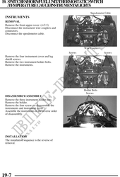
Speedometer Cable
INSTRUMENTS
REMOVAL
Remove the front upper cover. ( 2-5)
Disconnect the instrument wire couplers and
connectors.
Disconnect the speedometer cable.
Wire Couplers
Screws Screws
Remove the four instrument cover and leg
shield screws.
Remove the two instrument holder bolts.
Remove the instruments.
Holder Bolts
Screws
DISASSEMBLY/ASSEMBLY
Remove the three instrument holder nuts.
Remove the holder.
Remove the four screws to disassemble the
instruments and instrument cover .
Assemble the instruments in the reverse order
of disassembly.
INSTALLATION
The installation sequence is the reverse of
removal.
19-7