14.HANDLEBAR/FRONT WHEEL/FRONTBRAKE/
FRONT SHOCK ABSORBER/STEERING STEM DINK 50/125
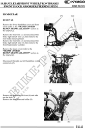
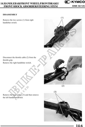
HANDLEBAR
REMOVAL
Remove the lower handlebar cover and front
cover (refer to the "FRAME COVERS
REMOVAL/INSTALLATION" section in
the chapter 2).
Remove the two bolts (1) and disconnect the
brake light switch wire (2), then remove the
rear brake master cylinder.
Remove the two bolts (3) and disconnect the
brake light switch wire (4), then remove the
front brake master cylinder.
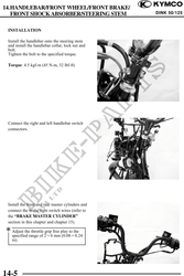
Remove the inner cover (refer to the
"FRAME COVERS
REMOVAL/INSTALLATION" section in
the chapter 2).
Disconnect the right and left handlebar switch
connectors (5).
Remove the handlebar lock nut (6) and take
out the bolt (7).
Remove the handlebar and collar (8).
14-4