dink 50 125 1 Werkstatthandbuch : Seite 95

Microfiches
Image preview

Seite 93

Image preview

Seite 94

Image preview

Seite 96

Image preview

Seite 97

1 5 10 15 20 25 30 35 40 45 50 55 60 65 70 75 80 85 90 95 100 105 110 115 120 125 130 135 140 145 150 155 160 165 170 175 180 185 190 195 200 205 210 215 220 225 230 235 240 245 250 255 260 265 270 275 280 285 290 295 300 305 310 315 320 325 330 335 340 345 350 355 360 365 370 375 380 385 390 395 400 405 410 415 420 424
          4. LUBRICATION SYSTEM                                                           DINK 50/125


                                                    Outer Rotor            Inner Rotor
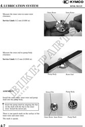
 Measure the inner rotor-to-outer rotor
 clearance.

 Service Limit: 0.2 mm (0.008 in)


 Measure the rotor end-to-pump body
 clearance.

 Service Limit: 0.12 mm (0.0048 in)


                                                     Pump Body             Rotor End


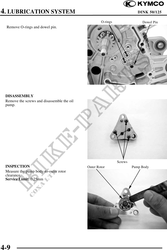
 ASSEMBLY                                          Dowel Pin               Pump Body


 Install the outer rotor, inner rotor and pump
 shaft into the pump body.

 Insert the pump shaft by aligning the flat
    on the shaft with the flat in the inner
    rotor. Install the dowel pin.

 There is one punch mark on the surface of the
 inner rotor and outer rotor.
                                                 Outer Rotor Inner Rotor     Pump Shaft
 The mark is upside.


4-7