19. LIGHTS/METERS/SWITCHES DINK 50/125
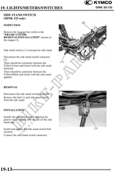
SIDE STAND SWITCH
(DINK 125 only)
INSPECTION
Remove the luggage box (refer to the
"FRAME COVERS
REMOVAL/INSTALLATION" section in
the chapter 2).
Side stand switch (1) is located on side stand
Disconnect the side stand switch connector
(2).
There should be continuity between the
Yellow/Green and Green with the side stand
retracted.
There should be continuity between the
Yellow/Black and Green with the side stand
applied.
REMOVAL
Disconnect the side stand switch connector.
Remove the bolt (1) and side stand switch
from the side stand.
INSTALLATION
Installs the side stand switch aligning the
groove on the switch with the pin on the side
stand stay.
Install and tighten the side stand switch bolt
securely.
Connect the side stand switch connector.
19-13