14.HANDLEBAR/FRONT WHEEL/FRONT BRAKE/
FRONT SHOCK ABSORBER/STEERING STEM DINK 50/125
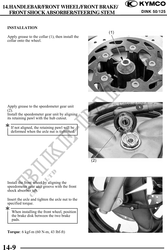
INSTALLATION
Apply grease to the collar (1), then install the
collar onto the wheel.
Apply grease to the speedometer gear unit
(2).
Install the speedometer gear unit by aligning
its retaining pawl with the hub cutout.
If not aligned, the retaining pawl will be
deformed when the axle nut is tightened.
Install the front wheel by aligning the
speedometer gear unit groove with the front
shock absorber tab.
Insert the axle and tighten the axle nut to the
specified torque.
When installing the front wheel, position
the brake disk between the two brake
pads.
Torque: 6 kgf-m (60 N-m, 43 lbf-ft)
14-9