17. IGNITION SYSTEM
A.C. GENERATOR INSPECTION
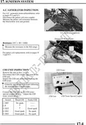
For A.C. generator removal/installation, refer
to pages 9-3 and 9-5.
Disconnect the pulser coil wire coupler.
Measure the pulser coil resistance between
the blue/yellow wire and ground.
A.C. Generator Connector
Pulser Coil Wire Coupler
Resistance (20): 80160
Measure the resistance in the X range.
For pulser coil replacement, refer to pages 9-
3 and 9-5.
CDI UNIT INSPECTION CDI Tester
Remove the met-in box. ( 2-3)
Disconnect the CDI coupler and remove the
CDI unit.
Inspect the CDI unit performance using the
CDI tester.
Correctly operate the CDI tester following
the manufacturer`s instructions.
Connect the CDI unit to the CDI tester
special coupler (KB7). Adjust the CDI
tester switch range. CDI Unit CDI Tester Special Coupler
Switch Good CDI Faulty CDI
1. OFF No spark
2. P
3. EXT Good spark
4. ON1 Good spark No spark
5. ON2 Good spark No spark
17-4