3. INSPECTION/ADJUSTMENT MXU 300/250
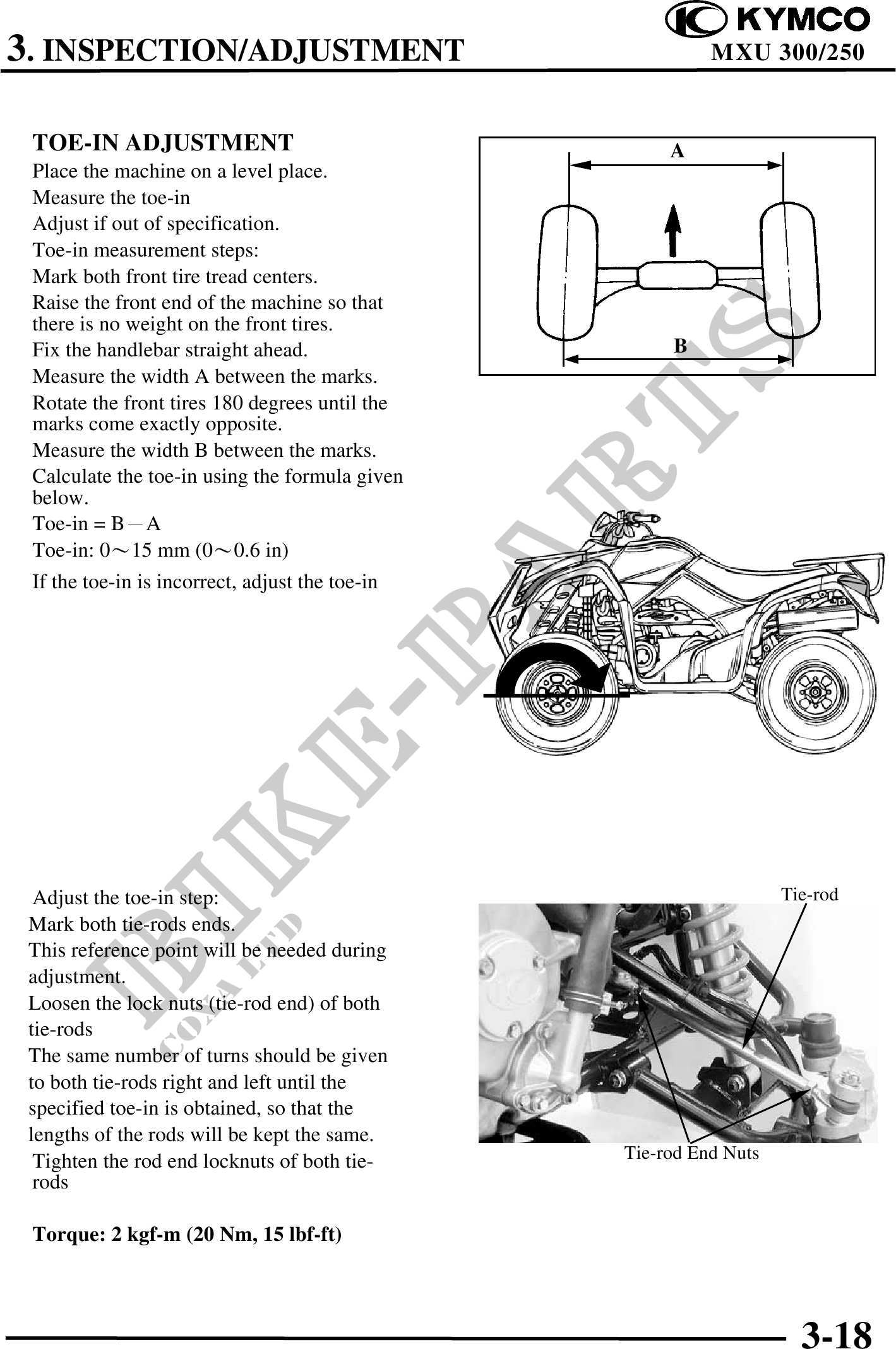
TOE-IN ADJUSTMENT A
Place the machine on a level place.
Measure the toe-in
Adjust if out of specification.
Toe-in measurement steps:
Mark both front tire tread centers.
Raise the front end of the machine so that
there is no weight on the front tires.
Fix the handlebar straight ahead. B
Measure the width A between the marks.
Rotate the front tires 180 degrees until the
marks come exactly opposite.
Measure the width B between the marks.
Calculate the toe-in using the formula given
below.
Toe-in = BA
Toe-in: 015 mm (00.6 in)
If the toe-in is incorrect, adjust the toe-in
Adjust the toe-in step: Tie-rod
Mark both tie-rods ends.
This reference point will be needed during
adjustment.
Loosen the lock nuts (tie-rod end) of both
tie-rods
The same number of turns should be given
to both tie-rods right and left until the
specified toe-in is obtained, so that the
lengths of the rods will be kept the same.
Tighten the rod end locknuts of both tie- Tie-rod End Nuts
rods
Torque: 2 kgf-m (20 Nm, 15 lbf-ft)
3-18